 During America’s Great Depression, a few areas of the country were unaffected. The oil fields in east Texas were such a place. In fact, the city of New London was booming. In 1932 the school district, one of wealthiest in the nation, had built a new, state of the art high school of steel and concrete. The football stadium was the first in the state to have electric lights. The school was built on sloping ground and a large air space was enclosed beneath the structure. The school board had overridden the original architect's plans for a boiler and steam distribution system, instead opting to install 72 gas heaters throughout the building. Early in 1937, the school board canceled their natural gas contract and had plumbers install a tap into Parade Gasoline Company's residue gas line to save money. This practice—while not explicitly authorized by local oil companies—was widespread in the area. The natural gas extracted with the oil was considered a waste product and was flared off. As there was no value to the natural gas, the oil companies turned a blind eye. Natural gas, untreated and in its natural state, is both colorless and odorless. Leaks could go undetected, or even unnoticed for quite some time. This was the case for the school. A leak had developed and filled the crawl space below the schools. In the days leading up to March 18, several students complained of nausea and headaches, but little attention was given at the time. March 18th was a Thursday. First through fourth grade were released early so older students could prepare for a scholastic and athletic competition in neighboring Henderson. A PTA meeting was being held in a separate building approximately 100 feet from the main building. Shortly after 3:00 pm, Mr. Lemmie R. Butler turned on an electric sander in an area unbeknownst to him was filled with a mixture of gas and air. The switch ignited the mixture and carried the flame along the air space below the school. The resulting explosion was heard four miles away and witnesses report that the building seemed to lift off the foundation and the walls bulged out before smashing back to the ground; throwing debris hundreds of feet and collapsing walls. Parents at the PTA meeting rushed to the main school building. Workers in the oil field and people in the community hurried to the school. Word of the explosion was relayed over telephone and telegraph lines. The Texas Rangers and highway patrol were dispatched to help aid. Workers began digging through the rubble looking for victims. Floodlights were set up, and the rescue operation continued through the night as rain fell. Within seventeen hours all victims and debris had been taken from the site. Mother Francis Hospital in Tyler canceled its elaborate dedication ceremonies to take care of the injured. The Texas Funeral Directors sent twenty-five embalmers. Of the 500 students and forty teachers in the building, approximately 298 died. Some rescuers, students, and teachers needed psychiatric attention, and only about 130 students escaped serious injury. Those who died received individual caskets, individual graves, and religious services. Of the 500 students and 40 teachers in the building 294 died. Only 130 students escaped serious injury. The tragedy became known as New London’s Lost Generation. A new hospital, Mother Frances Hospital in nearby Tyler, was scheduled to open the next day, but the dedication was canceled and the hospital opened immediately. Reporters who arrived in the city found themselves swept up in the rescue effort. Former Dallas Times Herald executive editor Felix McKnight, then a young AP reporter, recalled: "We identified ourselves and were immediately told that helpers were needed far more than reporters." Walter Cronkite also found himself in New London on one of his first assignments for UPI. Although Cronkite went on to cover World War II and the Nuremberg trials, he was quoted as saying decades later, "I did nothing in my studies nor in my life to prepare me for a story of the magnitude of that New London tragedy, nor has any story since that awful day equaled it.” Experts from the United States Bureau of Mines concluded that the connection to the residue gas line was faulty. The connection had allowed gas to leak into the school, and since natural gas is invisible and is odorless, the leak was unnoticed. These findings brought a hostile reaction from many parents. More than seventy lawsuits were filed for damages. Few cases came to trial, however, and those that did were dismissed by district judge Robert T. Brown for lack of evidence. While no school officials were found liable, public pressure forced the resignation of the superintendent (among talk of lynching), who had lost a son in the explosion. The most important result of the disaster was the passage of a state odorization law, which required that distinctive malodorants be mixed in all gas for commercial and industrial use so that people could be warned by the smell. Shortly after the disaster, the Texas Legislature met in emergency session and enacted the Engineering Registration Act (now rewritten as the Texas Engineering Practice Act). Public pressure was on the government to regulate the practice of engineering due to the faulty installation of the natural gas connection The use of the title "engineer" in Texas remains legally restricted to those who have been professionally certified by the state to practice engineering. 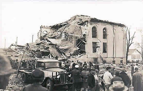 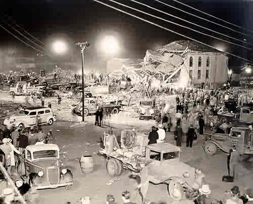
0 Comments
I've been working with AutoCAD longer than I care to mention. I'm used to selecting items in just a few ways:
1. Selecting object individually, by picking them. 2. Windowing around object(s). 3. Crossing object(s). 4.Using mulitpoint (polyshape) crossings. Which AutoDesk has made a little easier with their new selection tool. AutoCAD 2015 introduces a new option for object selection - "LASSO". Selecting objects by drawing a freehand boundary curve (similar to raster editors or Fusion 360) can be activated by pressing and holding the left mouse button and dragging along the requested boundary. Similarly to selecting with a rectangular window, dragging to the left invokes crossing selection, dragging to the right invokes full enclosing (the whole object must be caught in the lasso). Both modes can be toggled by pressing the spacebar during dragging (do not depress the mouse button). A second spacebar press switches to the Fence mode - will select objects intersected by a freehand curve you draw by dragging. I love the Match Properties command. It's a huge time-saver and I go to it often.
But there are still times when I don't need to match every property of an object--I just need to match a couple. For example: I may have text on two different layers, but I still need to match height and width. You can select which properties to match by following this link. You can file this under: Old Dog, New Tricks.
Annotative scale is a wonderful thing, allowing users to set up one Dimension Style and use that one style regardless of scale. It does take some getting used to. For example, if you change the scale of a viewport, then your dimensions will disappear. But AutoCAD University put out a paper on using Annotative Scale, and we present it to you now. The link is right here. Enjoy! Align (and Align/Scale, Align/Rotate) is not just a 3D tool. And it can certainly be handy. Check out the link to Robin's website. It's right here!
Give Align a try, and see what you've been missing. It took me a long time to realize the joy of using the Control and Shift keys when dealing with Windows. Apparently, it's taken me just a bit longer to realize all that the SHIFT key can do in AutoCAD.
1. SHIFT + LEFT mouse button: Will remove objects from your selection set, if you're selecting objects before issuing the command. ie, Select objects and then invoke COPY. 2. SHIFT + RIGHT mouse button: Brings up the OSNAP menu during many commands, as long as you have the RIGHT click option set up correctly in OPTIONS > USER PREFERNCES. 3. As we mentioned in an earlier post, if you want to FILLET or CHAMFER with a 0 distance, and not have to reset your radius or distance, you can: Pick your first line. Hold down the SHIFT key and pick the second line. This will fillet (or chamfer) with zero radius without changing the preset fillet radius. 4. You can also hold down the SHIFT key while using TRIM or EXTEND and it will perform the opposite command. Select TRIM and choose the line to trim back to. Trim several lines. Hold down the SHIFT key and pick a line and they will EXTEND to the trim line. 5. SHIFT + WHEEL/MIDDLE mouse button will start a 3D Orbit around your model as you move your mouse. When I first started in AutoCAD, there was only DText. One line of text at a time, and none of it tied together. Years ago, MText was introduced and now user could write multiple strings of texts (paragraphs) and it would be one entity. Once in a while, you'll have notes, call outs or titles that lay right on top of lines in a drawing. Much like we just showed in dimensioning, it's nice to not break lines, but still have a nice looking drawing. Using the same example as last week, you can see that we have a moment connection end plate, and this note is also directly 'on top' of the foundation footing. 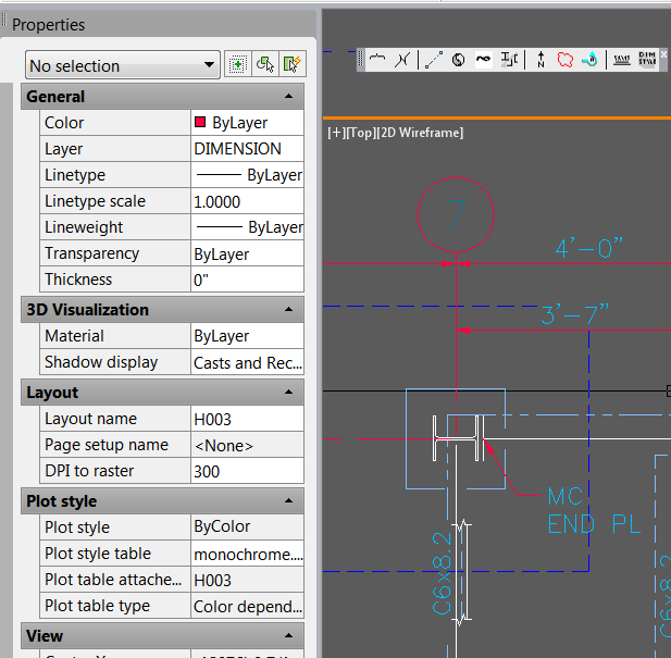 But since this text is MText, we can tell AutoCAD to hide items beneath it. Start by selecting the text and opening the Properties Box. Under the TEXT header, you will see a call out for BACKGROUND MASK 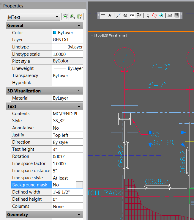 Select the '...' next to BACKGROUND MASK to open another Option Box. Check the box next to USE BACKGROUND MASK. You may need to set an Border Offset Factor. Generally, I choose a number between 1.25 and 1.5 Make sure you check USE DRAWING BACKGROUND COLOR. 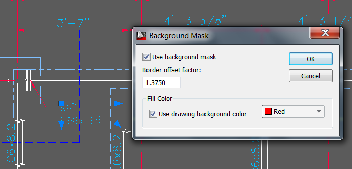 Select OK to close out the Background Mask Option box. You can grab a GRIP to elongate, or shorten the text box if desired. 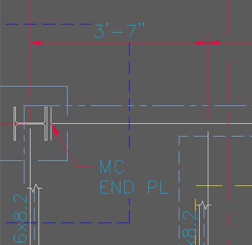 We've all run in to situations where our dimension text run right on top of some line or circle that we would rather not have there. Something like this: 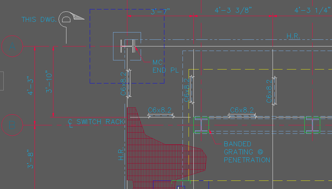 Our 3'-7" dimension is right out top of a foundation footing. Since this is a steel drawing, it needs to be shown, but in the old days we might just break the footing hidden line. In more recent years, Autodesk has given us a wonderful part of the dimension properties. We can hide something behind the dimension text and move away from break up items in the drawing. Open your Dimension Style manager, and click on the TEXT tab. The third item down, you'll see listed as FILL COLOR, and the default is NONE. 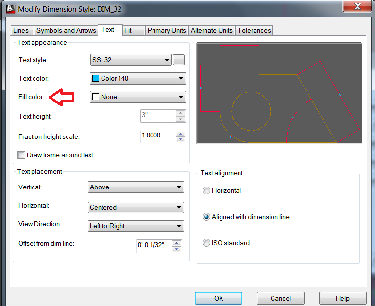 Click on the down arrow next to NONE and you'll be given a series of choices. To simply blank out anything behind your dimension text, select BACKGROUND 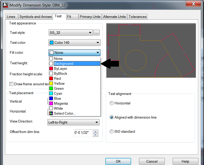 Select OK and CLOSE to get back out of the manager. And you will see that you've updated the dimension setting. 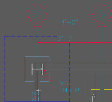 From - AutoDesk
Complex linetypes are custom linetypes that can contain embedded shapes or text. Before you create complex linetypes using text, consider how the font settings, scaling, and colors will affect the linetype. Text style settings The text height setting will affect the linetype if it is set to a specific height other than zero (0). No other text style settings will apply, unless multiline text is placed in the drawing using the same text style defined in the complex linetype. You must use the REGEN command to see the changes. Note: Use a text editor such as Notepad to create the complex linetype. If you try to create the linetype within the program, the following error message is displayed: INVALID number or bad continuation Before you create a linetype with text in it, define the text style that you will use. Unless the text style used in the linetype has been defined in the current drawing, the following error message (or similar) is displayed when you try to load the line: Bad definition of (linetype name) at line (line#) of file c:\Acltwin\filename.lin Note: You will also receive this message if there is not a hard return, or <enter>, placed at the end of the file that you have created. If you plan to use the LTSCALE or CELTSCALE command in the drawing, the text will change to the new size. Unless you follow these rules, it will shift out of alignment with the dashes that you have created.
The following exercise will demonstrate how to create a complex linetype and change the scale proportionally. Exercise When you create the complex linetype, you will assign the actual text height for the "S" transform. The linetype transform values S= (text height) and Y= (Y offset) are for centering the characters. If the S=1, then you will want to offset Y=.5 to center the line. Tip: You may want to place a line of text with mtext first and use the distance command to check the character height. Some fonts adhere to standards which may cause the center to be off.
Now try CELTSCALE set to 2 and place a new line on the screen. The dashes stay in proportion to the text and everything will scale together. Linetype defined A closer look at the linetype will tell what each part means. Each item is separated by commas. *MAP,--- Map --- where
where
Color The complex linetype must be only one color. It can be set to color bylayer or to any color using Entity Creation mode. The text is part of the line and not a separate entity. A complex line cannot be exploded. Shape files Compiled shape files (SHX files) can be used in complex linetypes. These SHP and SHX files must be created in the full version of AutoCAD. The location of the SHX file must be set in the support path. Use the instructions in the AutoCAD Customization Guideunder "Linetype Definition Files." An AutoCAD drawing that contains such a linetype must be accompanied by the compiled shape file or SHX file where the shape is defined, as well as the LIN file where the linetype is defined. Tip: For more information about complex linetypes refer to Help. Sometimes it's the little things. This part of the command has been around for awhile, but it's hard to get used to something new.
When you use the offset command, the new object always ends up on the same layer as the source object. That's the default option but you can have objects offset to the current layer. Start the Offset command, ModifyOffset from the pull-down menu or OFFSET from the command line. At the prompt, enter L for "Layer" and then C for "Current". Now, each time you use Offset, objects will be created on the current layer. To set Offset back to the default, use the same sequence but enter S for "Source". |
AuthorAutoCAD Tips provided each Wednesday. Archives
March 2016

|
 RSS Feed