|
We've all run in to situations where our dimension text run right on top of some line or circle that we would rather not have there. Something like this: 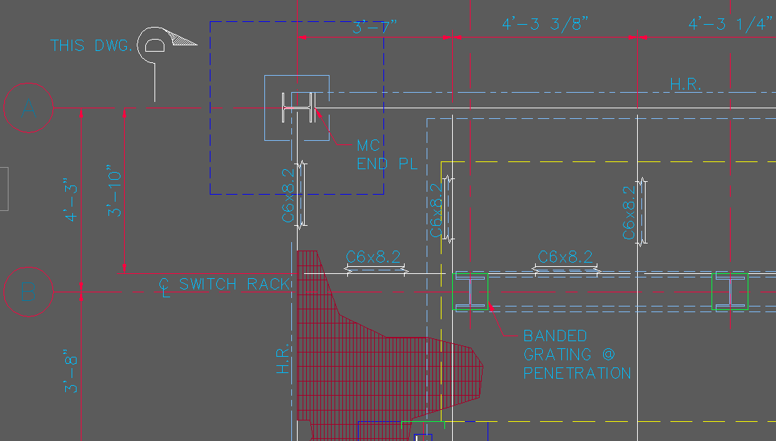 Our 3'-7" dimension is right out top of a foundation footing. Since this is a steel drawing, it needs to be shown, but in the old days we might just break the footing hidden line. In more recent years, Autodesk has given us a wonderful part of the dimension properties. We can hide something behind the dimension text and move away from break up items in the drawing. Open your Dimension Style manager, and click on the TEXT tab. The third item down, you'll see listed as FILL COLOR, and the default is NONE. 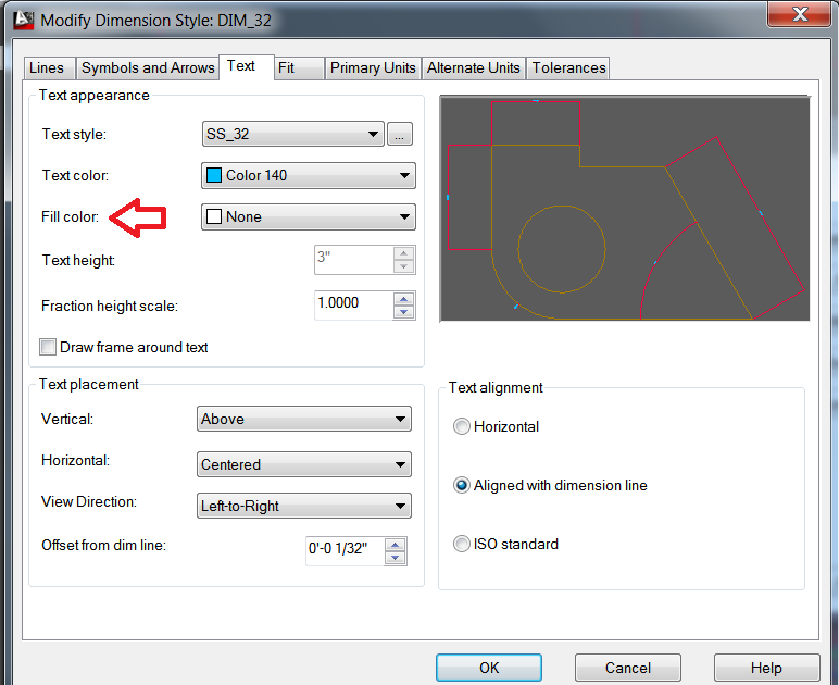 Click on the down arrow next to NONE and you'll be given a series of choices. To simply blank out anything behind your dimension text, select BACKGROUND 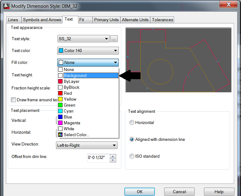 Select OK and CLOSE to get back out of the manager. And you will see that you've updated the dimension setting. 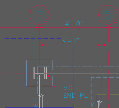
0 Comments
From - AutoDesk
Complex linetypes are custom linetypes that can contain embedded shapes or text. Before you create complex linetypes using text, consider how the font settings, scaling, and colors will affect the linetype. Text style settings The text height setting will affect the linetype if it is set to a specific height other than zero (0). No other text style settings will apply, unless multiline text is placed in the drawing using the same text style defined in the complex linetype. You must use the REGEN command to see the changes. Note: Use a text editor such as Notepad to create the complex linetype. If you try to create the linetype within the program, the following error message is displayed: INVALID number or bad continuation Before you create a linetype with text in it, define the text style that you will use. Unless the text style used in the linetype has been defined in the current drawing, the following error message (or similar) is displayed when you try to load the line: Bad definition of (linetype name) at line (line#) of file c:\Acltwin\filename.lin Note: You will also receive this message if there is not a hard return, or <enter>, placed at the end of the file that you have created. If you plan to use the LTSCALE or CELTSCALE command in the drawing, the text will change to the new size. Unless you follow these rules, it will shift out of alignment with the dashes that you have created.
The following exercise will demonstrate how to create a complex linetype and change the scale proportionally. Exercise When you create the complex linetype, you will assign the actual text height for the "S" transform. The linetype transform values S= (text height) and Y= (Y offset) are for centering the characters. If the S=1, then you will want to offset Y=.5 to center the line. Tip: You may want to place a line of text with mtext first and use the distance command to check the character height. Some fonts adhere to standards which may cause the center to be off.
Now try CELTSCALE set to 2 and place a new line on the screen. The dashes stay in proportion to the text and everything will scale together. Linetype defined A closer look at the linetype will tell what each part means. Each item is separated by commas. *MAP,--- Map --- where
where
Color The complex linetype must be only one color. It can be set to color bylayer or to any color using Entity Creation mode. The text is part of the line and not a separate entity. A complex line cannot be exploded. Shape files Compiled shape files (SHX files) can be used in complex linetypes. These SHP and SHX files must be created in the full version of AutoCAD. The location of the SHX file must be set in the support path. Use the instructions in the AutoCAD Customization Guideunder "Linetype Definition Files." An AutoCAD drawing that contains such a linetype must be accompanied by the compiled shape file or SHX file where the shape is defined, as well as the LIN file where the linetype is defined. Tip: For more information about complex linetypes refer to Help. Sometimes it's the little things. This part of the command has been around for awhile, but it's hard to get used to something new.
When you use the offset command, the new object always ends up on the same layer as the source object. That's the default option but you can have objects offset to the current layer. Start the Offset command, ModifyOffset from the pull-down menu or OFFSET from the command line. At the prompt, enter L for "Layer" and then C for "Current". Now, each time you use Offset, objects will be created on the current layer. To set Offset back to the default, use the same sequence but enter S for "Source". If you're new to AutoCAD or even if you're not and you find it difficult to remember all the keyboard shortcuts to your favorite commands like L for Line and C for Circle or even 3DO for 3DOrbit, then you need to know about the AutoCAD Alias Editor.
Enter ALIASEDIT at the command line and AutoCAD will launch a tiny application window that lists all the shortcuts in alphabetical order. As this is a seperate application, you can keep it minimised on your taskbar until you need it for reference. Essentially, this editor simply lists the contents of the acad.pgp file where all the command aliases are stored. Those of you who are a bit more adventurous, may even like to use the Alias Editor to create your own aliases or edit existing ones. I, for example, hardly ever use the DRAFTSETTINGS command (alias command DS). I updated the alias so that when I type in DS AutoCAD starts a LiSP routine to create a new DimStyle. If you find yourself using the same combination of commands and options over and over, you can easily create a custom command that executes the combination with a click of a button or a menu item. In this tutorial, I explain the basics of AutoCAD’s menu syntax so that you can create your own commands. No programming required!
< Space > Equivalent to pressing Enter except when entering text to create a text object that contains spaces (between words). Use between the command and its options. ; (semi-colon) Equivalent to pressing Enter. The end of a line in a menu macro is also equivalent to pressing Enter. More helpful than using a space when you need to press Enter twice, because it shows the number of Enters more clearly. Also helpful at the end of the macro. \ Pauses for user input, such as picking a point or entering a value. + At the end of a macro line, continues the macro to the next line * At the beginning of a macro, before ^C^C, repeats the macro until you press Esc or choose another menu item. ^P Toggles the display of the menu macro on the command line; makes the macro look neater when you use it. I really like using AutoCAD's LENGTHEN command. And when I use it, I *only* use it Dynamically, so I've created a new macro into a new button that I can use that will automatically start the Lengthen command and step through the selection of Dynamic and let me pick that line that I want to work on. 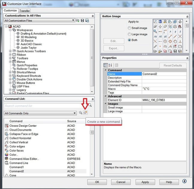 First, type CUI to bring up the Customize User Interface, and then select the CREATE A NEW COMMAND button as shown above. A new command will be created called COMMAND1 (or COMMAND2, or COMMAND3...) Select the COMMAND1 command from the Command List pane, just below you Create A New Command button. This will populate the PROPERTIES area for the command. 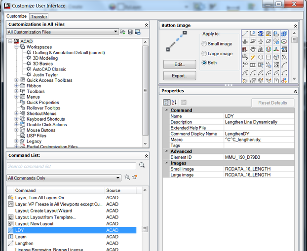 Under PROPERTIES I called my new Command LDY and wrote a brief description. At the MACRO area it reads: ^C^C_lengthen;dy; [which basically tells AutoCAD Cancel Cancel. Start the LENGTHEN command <enter> DYnamic <enter> I also stole the default lengthen button image. 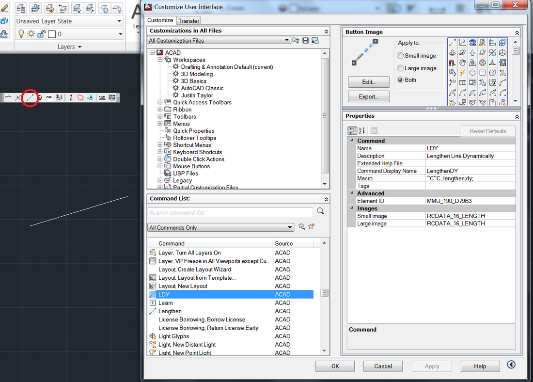 Lastly, I added my new command to a newly created Toolbar Menu. You can add your new command to any Toolbar menu.
AutoCAD allows users to add and change its interface. Several years ago, if you worked on a tablet, you could create your own menus easily. It has gotten a little more tedious as AutoCAD has evolved. I find the CUI (Client User Interface) a little harder to manipulate. Over the next few Tips, we'll look at changing a few menus and commands. Auto Repeating Commands Sometimes you need to repeat a command lots of times and it can be a bit tedious doing the usual Right-Click and Repeat… or even using the Enter key on the keyboard. It would be really useful if you could just keep a command auto-repeating until you hit the Escape (Esc) key. Well, you can. All you need to do is make a small change to the CUI. For example, say you want to draw lots of circles and have the circle command auto-repeat so that you can just pick center, radius, center, radius etc. Here's what you do:
This technique can be used with most commands. For example, if you are doing a lot of dimensioning, you could auto-repeat the Linear Dimension command so that you can draw all your dimensions without breaking stride. 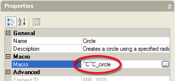 We love viewports (or MView). The zoom factor of your viewports is crucial because it affects the plotted scale of your drawing. So, once you have set your viewport scale, it's a good idea to lock your viewport so that you don't inadvertently change it. To lock a viewport, select it in paper space by picking on its boundary and then right-click anywhere within the viewport. Select "Properties" from the right-click menu and the Properties panel will appear. In the "Misc" section, click on "Display locked" to activate the pull-down and set the value to "Yes".  To really maximize your work area, try CLEANSCREEN. You can use Ctrl+0 (that's a zero), or go to ToolsClean Screen, or click the faint blue square icon at the very bottom right of the AutoCAD program window to maximize your entire work area. The only thing that will show is your top Pull-down Menu, your Command Line, and/or your Layout Tabs, maximizing the drawing area as much as possible. Of course, you could also turn off the command line and just work with Dynamic Input if you wanted to be even more minimal. These command options work as a toggle, so simply repeat the action to restore the full interface.  If you are a customized keyboard command type of person, the command is CLEANSCREENON and CLEANSCREENOFF so you can easily add it into your ACAD.PGP file complete with your personal Command Alias.
|
AuthorAutoCAD Tips provided each Wednesday. Archives
March 2016

|
 RSS Feed